Hencher Associates Limited
Hencher Associates Limited  

Direct Shear Testing of Rock Discontinuities and Scale Effects

There is a lot of confusion regarding the direct shear testing of rock discontinuities and discussion and publications are presented here to read and download.  The first download is a presentation on shear strength of rock joints and it makes reference to various papers that can be downloaded here. 

Shear Strength of Rock Joints HK compres[...]
Adobe Acrobat document [16.6 MB]
Hencher Richards (1982).pdf
Adobe Acrobat document [13.2 MB]
Richards Cowland 1986.pdf
Adobe Acrobat document [1.8 MB]
Hencher 1995.pdf
Adobe Acrobat document [3.0 MB]
Hencher Richards Manuscript 2015.pdf
Adobe Acrobat document [6.1 MB]

Yip Kan Street Failure 1981


The document below provides data on a series of direct shear tests carried out as part of an investigation into a large rock slope failure at Yip Kan Street, Hong Kong in 1981. The report itself, together with an Appendix setting out the reasoning for stress levels for testing are provided under the section on landslide case histories. The case was interesting as it involved sliding on joints dipping at only about 20 degrees which is much lower than the friction angle measured for saw cut surfaces through the parent rock. The failure occurred on a dry Sunday when there were no blast vibrations from the adjacent construction site - the plot thickens!!!


The tests were conducted on matched and mis-matched rock joint samples using a Golder Associates Shear Box. Data were collected manually rather than electronically with three people reading the displacement and load gauges simultaneously at very frequent intervals. We developed a method whereby any of us could say "now" to take a set of readings. Electronic testing is much easier and nowadays at Leeds University, there is a motorised Golder Box that was used for the testing described by Hencher & Richards (2015). For the tests described for Yip Kan Street, most were multistage with normal load being progressively increased. For others, loading stages were decreased, experimentally to investigate the effects of damage. Similar experiments are described in the presentation downloadable above. Apologies for size of file, but photos are good and it helps to understand the importance of proper sample description and documentation which is unfortunately lacking in most commercal tests I see. 


The Head of the Geotechnical Engineering Office and the Director of the Civil Engineering and Development, the Government of the Hong Kong Special Administrative Region are thanked for their permission to reproduce the report. The Government of the Hong Kong Special Administrative Region does not accept responsibility for the accuracy, completeness or up-to-date nature of the material.

Yip Kan Street Failure, 1981 Appendix A.[...]
Compressed archive in ZIP format [94.4 MB]

Tilt Tests - Eric Laithwaite and the Jabberwocky

My PhD research at Imperial College, London concerned friction of rock joints under dynamic loading such as from earthquakes or blasting. The work was largely experimental using a tilting table, set at specific inclinations and then applying vibration loading either in the lab using the table set on runners and impacted by spring loading or in the field using blasts and dynamic compaction as the source for the dynamic loading. The set up was similar to that used by Seed and Goodman on sands.


The laboratory set up had the tilt table with a base slab and sliders. The input vibration from spring sets of different stiffnesses was measured on the table using an accelerometer. the displacment of sliders against time was measured using a relatively high speed film camera. The timing of the movements was critical and co-ordinated using a stop watch (in the film image) and the accelerometer records and all records were correlated using a cumputer programme (TIMINGS) to minimise reading errors. 


Once the apparatus was designed and constructed by the excellent lab technicians Ted Rogers and Brian Clarke, of whom I have videos, and will insert at some stage, the first experiments were used to check the mechanics and, to this end, blocks of wood of different geometries were used together a sliding base also of wood. It was straightforward to calculate at what accelerations each of the different blocks should topple under the horizontal acceleration. At the time I was under the illusion that basic friction, say between wood and wood, was a constant, so was a bit surprised when I found that some of the taller blocks could not be placed at certain inclinations but slid at lower angles than more squat blocks. I was wondering about this and consulted Dr John Bray, along the corridor from my experiment, when a colleague pointed out that Professor Eric Laithwaite who was then Professor of Heavy Electrical Engineering at Imperial College, had demonstrated something similar in his lectures to the Royal Institution. Professor Laithwaite  was gracious enough to invite me to his office to have coffee and discuss my findings.


Professor Eric Laithwaite

Professor Laithwaite was an amazing and very open-minded British scientist. His lectures at IC were standing room only. He was largely responsible for the design of the linear motor and Maglev trains. He also became fascinated with gyroscopes and his Christmas Lectures to the Royal Institution, that can be found on YouTube, are fascinating, as is the written record of the ones in 1974 published as "Engineer through the Looking Glass".


My memory of meeting Professor Laithwaite remains strong and vivid. He sounded like Eric Morecombe and was entirely approachable and funny with it. I explained my findings on sliding friction and he was not in the slightest surprised. He argued that there are extremes of impossibility but anything in between was essentially fair game. His opinion was that most physical equations are only there so that exam questions can be set. He also suggested, perhaps tongue in cheek, that the plethora of small atomic particles that were then being discovered, might be the result of rounding up errors in the maths.


His Faraday Lecture to the Royal Institution where he demonstrated some of the qualities of gyroscopes was never published and his nomination for Fellowship of the Royal Society cancelled. What a great shame. The Times obituary following his death in 1997, quoted him thus: "I thought my fellow scientists would be genuinely interested, so I wasn't prepared for the utter hostility of their reaction"


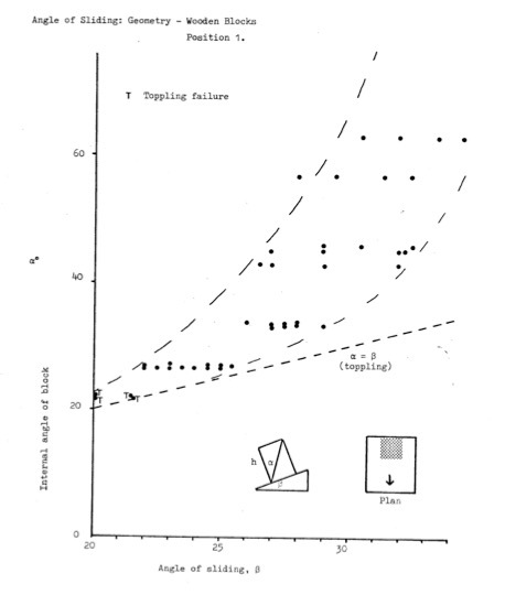
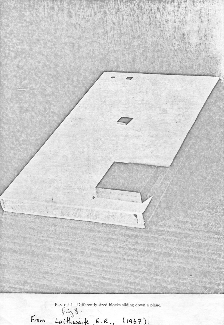
He published the figure on the left in 1967, I think associated with his first Christmas Lectures. He was discussing scaling of linear motors but noted that "friction does not scale as nicely as the elementary textbooks would have you believe". He used brass blocks, all to scale and found that the largest (heaviest) slid first following by the others in order. In his later lectures in 1974 (available on-line), which was about the time that I met him, he showed that adding some jam between blocks and planes meant that the smallest block could stand vertically and even beyond. This is of course not really just friction but involves cohesion/adhesion but his demonstrations of blocks sliding on a plane at different angles certainly showed that the commonly held belief that there is a single basic angle of friction is rather a simplification.

Systematic Tilt Tests using wooden blocks and steel weighted rock slices.

Following the initial observation that tall blocks of wood slid at lower angles of inclination than squatter blocks, I carried out a series of repeated tests with the results as shown on the right. I also tried tests with blocks set up with point leading down slope rather than edge. The results were different and this all came as a surprise. The results are presented and discussed in Chapter 5 Part 1 from my PhD thesis that can be found below.


This series of experiments were followed by tests using four different rock types using large basal blocks of the rock, saw cut and ground with different grades of carborundum powder and sliders of rock attached to steel blocks. It was found that angles of sliding varied widely depending on whether rock flour debris was left to accumulate on the surface or not. For most rocks, it was found that the lower bound,  'basic' friction varied considerably with cumulative distance of sliding, reducing eventually to somewhere around 12 degrees (from a start of about 32 degree). If debris was then allowed to accumulate, the sliding angle went back up again towards 30 degrees! Blowing away the dust reduced it again. Turning a block around before sliding changed it again. These results were reported in Chapter 5 Parts 2 to 4 of my thesis (below) and formed the basis of a discussion paper to Geotechnique (also below). In summary, the frictional resistance of planar surfaces of rock can vary between about 10 and 40 degrees depending on the surface finish. These results went largely unnoticed until recently where Prof Leano Alejano at the University of Vigo and colleagues have produced similar results. In my view the tilt test is only useful for demonstrating the true nature and source of frictional resistance rather than for any design purpose, but the test results are certainly interesting.

Tilt Tests

Chapter 5 Part 1 wood tests.pdf
Adobe Acrobat document [4.6 MB]
Chapter 5 Part 2 1st rock tests.pdf
Adobe Acrobat document [3.5 MB]
Chapter 5 Part 3 2nd rock tests.pdf
Adobe Acrobat document [3.8 MB]
Chapter 5 Part 4 3rd rock tests.pdf
Adobe Acrobat document [968.0 KB]
Rock mechanics discussion 2012.pdf
Adobe Acrobat document [391.1 KB]

Dynamic tilt tests

As noted earlier, the prime purpose of my research at IC was to investigate frictional resistance under dynamic loading; the static tilt test programme was a necessary but unexpected precursor. The results from the dynamic tests are discussed in Section 7 of my thesis and summarised in a paper dated 1981. Again these results, which were quite significant for understanding the nature of friction, have been largely ignored but that is the way of science I am afraid. I will add more to this page and include some of the experimental data (filmed experiments).

Chapter 7.pdf
Adobe Acrobat document [8.8 MB]
Hencher 1981 friction parameters earthqu[...]
Adobe Acrobat document [736.6 KB]

Scale Effects

Hencher, Toy Lumsden 1993.pdf
Adobe Acrobat document [10.9 MB]

Direct Shear Test Analysis on Real Rock Joints

Discussion on test analysis (for tests at constant normal load) is presented in the down-loadable papers above

See Hencher & Richards (1989) for a concise discussion on how tests should be documented and conducted.

When testing rough joints it is essential to measure, concurrently, shear load, normal and shear displacement. This is because where overriding roughness features (dilating) the measured strength will increase; conversely where contracting the measured strength will be less. That being so test data are specific to particular test samples and the same sample, set up in a different way, will give different results.  


If one simply carries out a lot of tests on variable samples without accounting for sample-specific roughness that you will simply get a scatter plot that is useless. One needs to adjust for the dilation and contraction continually occurring throught the test (see Hencher & Richards (2015), downloadable in manuscript form above and published in Rock Mechanics and Rock Engineering 

  • Hencher, S.R. & Richards, L.R. Rock Mech Rock Eng (2015) 48: 883. doi:10.1007/s00603-014-0633-6
  •  

To do this one needs to calculate dilation or contraction angles and adjust the shear and normal stress. This can be done manually (as it was for the results discussed in Hencher & Richards (1982)). However if collecting data using LVDTs and load cells at very small increments of displacement then a decision needs to be made over which displacement to make corrections. This is discussed in Hencher (2015) Practical Rock Mechanics (not downloadable I am afraid). Generally a displacemnt interval of about 0.2 mm works pretty well. I have written a programme to do this and you can replace the raw data with your own or just play around with the data I have here. The programme is still a bit 'clunky' and could certainly be improved upon given a bit of programming time. If anyone does tthis please let me know.


Anyway, I provide this programme without any warrenty of its fitness for purpose or accuracy, as research in progress. Incidentally I also have drawings (requiring some checking) for the original Golder Associates shear box that is unfortunately unavailable commercially but much better than any other shear box I have encountered for either research or real project work. I have permission from Golder Associates to make these available so please contact me if you want copies - this may well be suitable for universities intending to carry out research on discontinuity shear strength. At Leeds University  several of these machines were constructed, with modifications including a motorised version.


ANALYSIS DRAFT SPREAD SHEET.xlsx
Microsoft Excel sheet [494.7 KB]
Print | Sitemap
© Hencher Associates Limited